The leap sheep cheating machine
Plays the game so you don't have to...

The leap sheep cheating machine
Plays the game so you don't have to...
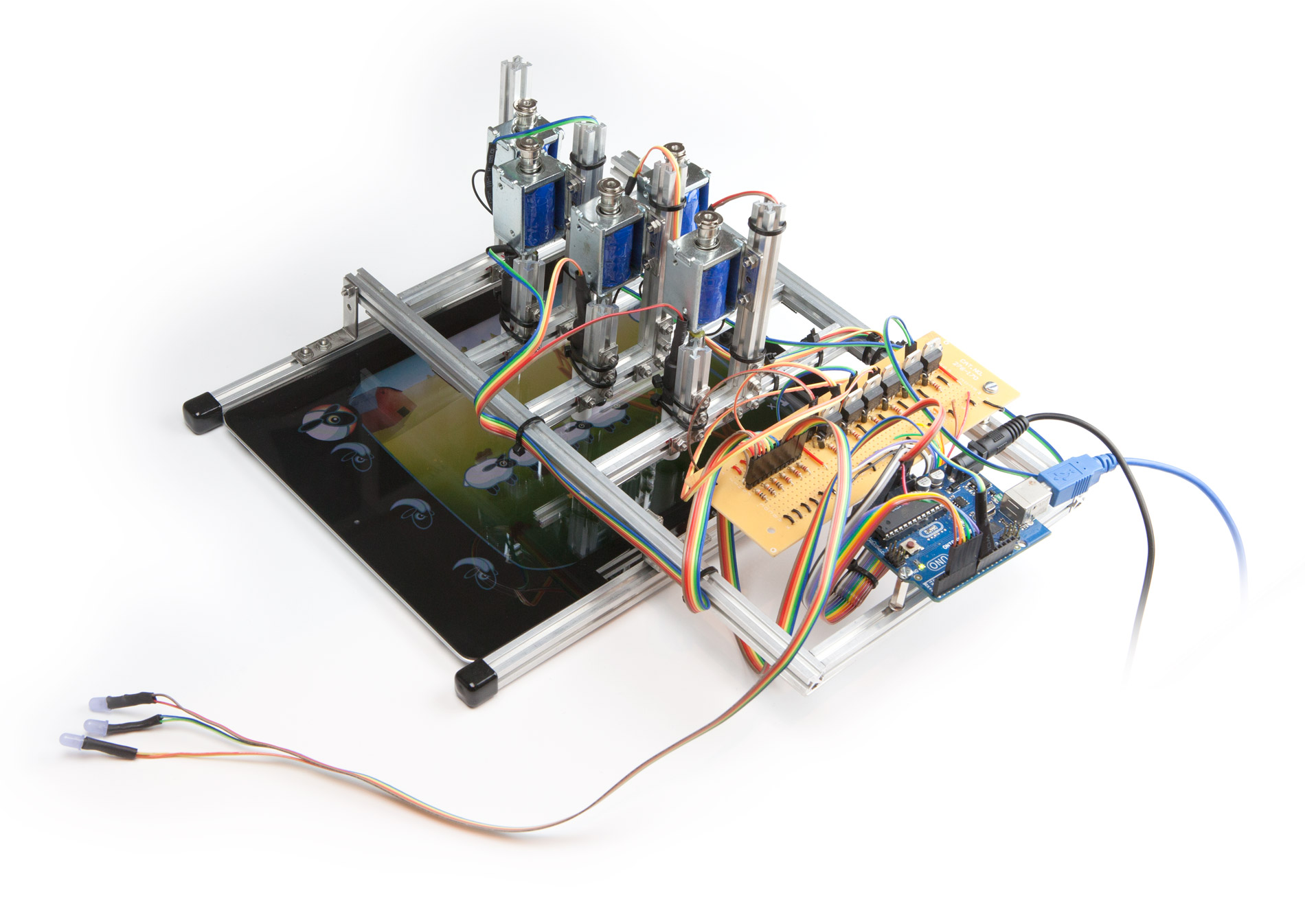
A light sensor measures the brightness of each lane. The Arduino / computer store these values and use them to work out if there's a sheep currently under the sensor. It then predicts when the sheep will arrive and fires the solenoid to tap them over the fence!

On a complete whim about 2 years ago, I decided to make a robot to autonomously play one of my favourite iPhone games: Leap Sheep. The game's nice and simple so lends itself really well to automation. Sheep run from left to right, and to play, all you need to do is tap them before they crash into the fence.
Working on the project on and off, I’ve now built the robot three times! The first attempt was designed to play an iPhone and was programmed in C. It worked, just about, but the code got a bit out of hand and I struggled to fit everything into the space. About a year later, I picked the project up again and rebuilt it to play an iPad instead. I also decided to tether the Arduino to my computer so I could program in Python. It was an improvement but wedding plans took over and I never finished it. This year I decided to have one last go, and rewrote the code from scratch a second time using Javascript and Node. It's still not quite as reliable as I'd like, and I'm still making improvements, but it's getting there!
Note: I could pretend there was some deep meaning to a machine designed to play a game for you, but there's not. I'm just an engineer (sort of) who wanted to build a robot!
Before doing anything else, I needed to check it was possible to detect sheep and trigger the screen.
My hunch was that a simple light dependent resistor (LDR) would be able to detect changes in brightnesses in the game. To check, I strapped an LDR to the screen and measured the resistance. Happily, it worked first time!
Triggering the screen split into two problems 1) How to simulate a finger 2) How to move the ‘finger’ up and down.
I’d read a weird article about how some Koreans were using sausages as styluses in the winter, because touch screens wouldn’t work through gloves, and so thought that simulating touch might be a problem.
To check, I held a stylus with some insulated pliers and found it didn’t work. I then conducted some very strange experiments involving carrots, before asking a question on the Electrical Engineering Stack Exchange and discovering that all you needed to do was ground the stylus!
For actuating the stylus, my initial thought was to use servos. However, translating the motion to linear and getting the timing and speed required, proved to be more or less impossible.
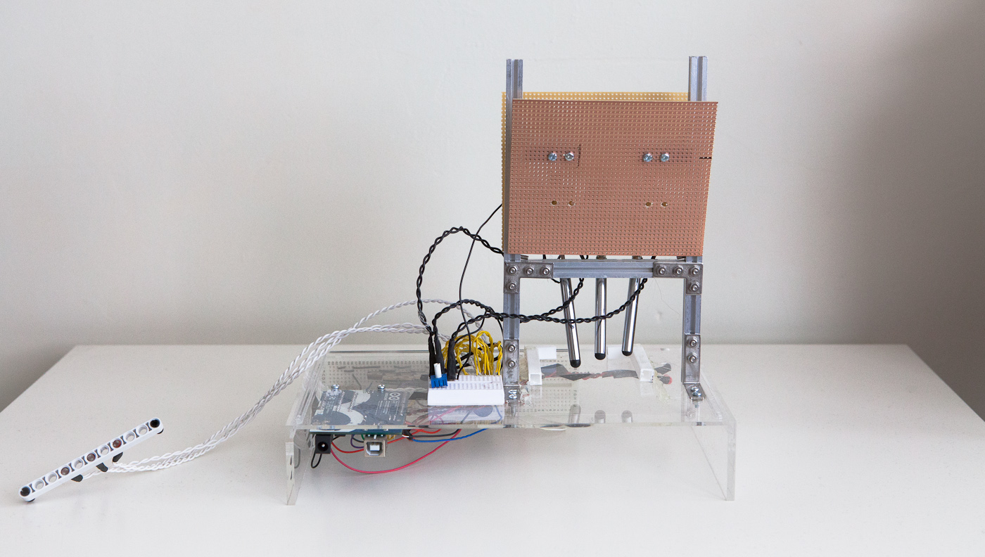
I therefore decided to buy some solenoids off eBay. They worked perfectly and, although they required a bit more circuitry, they also had the added benefit that they could be connected directly to the styluses.
I’d originally planned to build the chassis to hold the electronics and actuators completely from scratch, but I then discovered Makerbeam.
The first version of the robot only used the beams for the vertical supports, but I built the second and third iPad versions entirely using Makerbeam.
The structure was designed to allow the LDRs and solenoids to be repositioned easily, and for the whole robot to be lifted on and off the iPad to make it less of a hassle to operate the iPad.
At first I mocked up the electronics on a breadboard, before moving to stripboard. For the LDRs, I just had to set up 3 simple potential divider circuits and connect them to the Arduino’s analog inputs.
For the solenoids, I found a circuit on bildr.org (an excellent resource for learning how to use different sensors and components with the Arduino). Solenoids require more current than the Arduino can provide, so they need an external power source. Transistors allow the low power Arduino output to switch the high power supply on and off. A diode protects circuit from the back EMF caused by the solenoids discharging.

In my final build, I also added some LEDs to show when sheep were detected.
I did briefly consider modifying the design slightly to use two LDRs for each lane connected together in a Wheatstone bridge, to make it easier to detect sheep and work out their speeds - in the end it proved unnecessary.
After getting in over my head with programming directly on the Arduino with C, I decided to tether the Arduino to a computer and rewrite the application in Python. I installed Firmata on the board and then used the pyFirmata library to control it.
When I came back to the robot this year, as I’ve been trying to improve my Javascript skills, I decided to rewrite the application using the Johnny-Five framework.
Following some advice from a developer buddy, I decided to program the code in a basic loop. Every 50ms the application loops through each lane; reading the sensor values, deciding if any sheep have arrived, and working out whether the solenoid should be up or down.
The hardest part was accurately detecting the sheep. I couldn’t just set a fixed threshold as the ambient lighting changed too much and the game also varies to match the time of day! In the end, I found comparing a short rolling average to a longer one worked fairly reliably, although I’m sure I could have done something more intelligent.

By placing the LDRs as close as possible to the solenoids, I could neglect variations in sheep speed and size and reduce any errors in my calculations (although I may revisit this if I build the robot again!).
The most frustrating part of the process was testing the detection and solenoid timings. Exporting a log helped, especially with the sheep detection, but to get the timings right I had to run the game many, many times!
I tried adding a 4th sensor to help work out when the game was running, but this proved more trouble than it was worth and in the end I just added a keyboard input.
You can see the finished code on GitHub.
My original aim was to build a robot that was better at playing the game than a human. At the moment it’s not quite there.
The longest I’ve had it running continuously so far is about 5 minutes: 110 sheep. Occasionally it just misses a very fast or slow sheep, and because the solenoids are fixed there's no way for it to recover. I'm sure with a bit more tweaking I can get it to do much better, but I may have to add a second row of LDRs to more accurately measure the speed of each sheep. If that doesn't work, I might try using a webcam and Open CV instead of the LDRs.
Finally, if you're crazy enough, I'd like to challenge you to make your own Leap Sheep cheating machine. I've learned a lot building mine and I'd be fascinated to see other people's approaches!

I'm a mechanical engineering graduate turned product manager at a UK software company. I spend most my spare time making things like this or taking photos! www.tomrandle.com